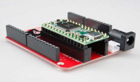
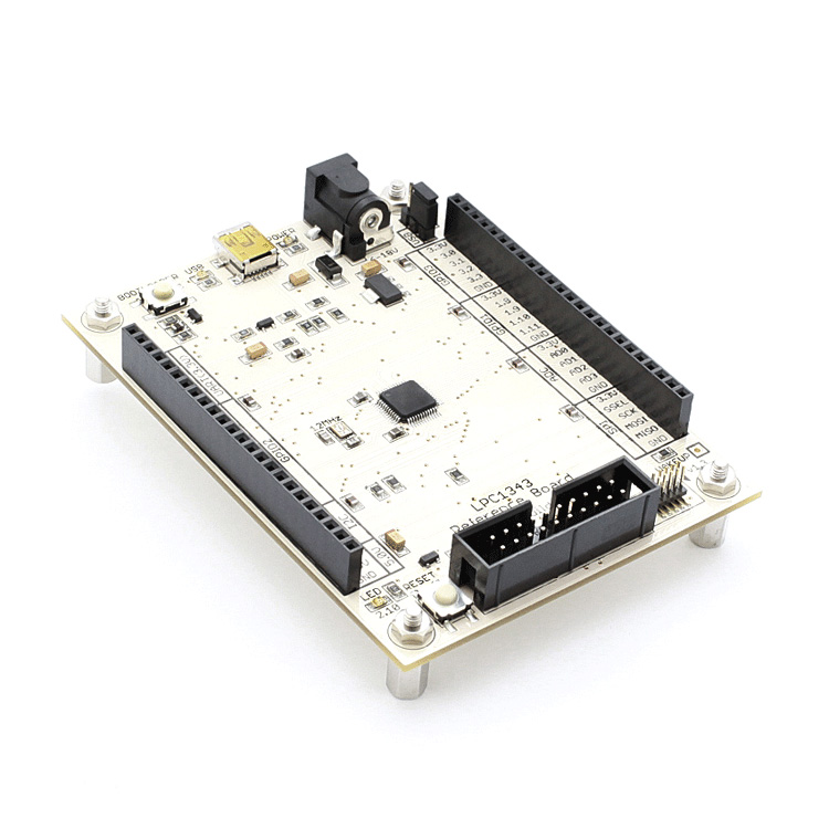
هدربرد Cortex-M3 LPC1343 یک سخت افزار اپن سورس می باشد که می توانید آن را تولید ،استفاده و تغییر دهید. هدربرد LPC1343 دارای مثال های متعدد و کامل می باشد و همچنین برای استفاده از این برد در پروژه های دیگر خود یک فایل فوت پرینت نیز طراحی شده است. خلاصه اگر می خواهید یک هدربرد مناسب برای میکروکنترلر قدرتمند Cortex-M3-LPC1343 داشته باشید ، تا در پروژه های خود استفاده کنید این برد مناسب می باشد.
میکروکنترلر LPC1343 (موجود در بازار ایران) یک میکروکنترلر ارزان قیمت (در هنگام نگارش این مقاله در بازار ایران 8 هزار تومان) از سری میکروکنترلرهای قدرتمند Cortex-M3 می باشد.که دارای 32KB حافظه فلش ، 8KB SRAM ، دارای پورت USB قدرتمند و فرکانس کاری حداکثر 72مگاهرتز که این میکروکنترلر را در جاهایی که پردازش زیاد به همراه USB نیاز است و قیمت تمام شده بسیار مهم است این میکروکنترلر یکی از بهترین انتخاب ها است.
ARM Cortex-M3 processor, running at frequencies of up to 72 MHz.
ARM Cortex-M3 built-in Nested Vectored Interrupt Controller (NVIC).
32 kB (LPC1343/13)/16 kB (LPC1342)/8 kB (LPC1311) on-chip flash programming
memory.
8 kB (LPC1343/13)/4 kB (LPC1342/11) SRAM.
In-System Programming (ISP) and In-Application Programming (IAP) via on-chip
bootloader software.
Selectable boot-up: UART or USB (USB on LPC1342/43 only).
On LPC1342/43: USB MSC and HID on-chip drivers.
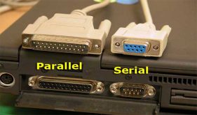
Serial interfaces:
USB 2.0 full-speed device controller with on-chip PHY for device (LPC1342/43
only).
UART with fractional baud rate generation, modem, internal FIFO, and
RS-485/EIA-485 support.
SSP controller with FIFO and multi-protocol capabilities.
Additional SSP controller on LPC1313FBD48/01.
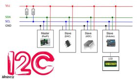
I2C-bus interface supporting full I2C-bus specification and Fast-mode Plus with a
data rate of 1 Mbit/s with multiple address recognition and monitor mode.
Other peripherals:
Up to 42 General Purpose I/O (GPIO) pins with configurable pull-up/pull-down
resistors.
Four general purpose counter/timers with a total of four capture inputs and 13
match outputs.
Programmable WatchDog Timer (WDT).
Programmable Windowed Watchdog Timer (WWDT) on LPC1311/01 and
LPC1313/01.
System tick timer.
Serial Wire Debug and Serial Wire Trace port.
High-current output driver (20 mA) on one pin.
High-current sink drivers (20 mA) on two I2C-bus pins in Fast-mode Plus.
Integrated PMU (Power Management Unit) to minimize power consumption during
Sleep, Deep-sleep, and Deep power-down modes.
Power profiles residing in boot ROM allowing to optimize performance and minimize
power consumption for any given application through one simple function call.
(LPC1300L series, on LPC1311/01 and LPC1313/01 only.)
Three reduced power modes: Sleep, Deep-sleep, and Deep power-down.
Single power supply (2.0 V to 3.6 V).
10-bit ADC with input multiplexing among 8 pins.
GPIO pins can be used as edge and level sensitive interrupt sources.
Clock output function with divider that can reflect the system oscillator clock, IRC
clock, CPU clock, or the watchdog clock.
Processor wake-up from Deep-sleep mode via a dedicated start logic using up to 40 of
the functional pins.
Brownout detect with four separate thresholds for interrupt and one threshold for
forced reset (four thresholds for forced reset on the LPC1311/01 and LPC1313/01
parts).
Power-On Reset (POR).
Integrated oscillator with an operating range of 1 MHz to 25 MHz.
12 MHz internal RC oscillator trimmed to 1 % accuracy over the entire temperature
and voltage range that can optionally be used as a system clock.
Programmable watchdog oscillator with a frequency range of 7.8 kHz to 1.8 MHz.
System PLL allows CPU operation up to the maximum CPU rate without the need for a
high-frequency crystal. May be run from the system oscillator or the internal RC
oscillator.
For USB (LPC1342/43), a second, dedicated PLL is provided.
Code Read Protection (CRP) with different security levels.
Unique device serial number for identification.
Available as 48-pin LQFP package and 33-pin HVQFN package.
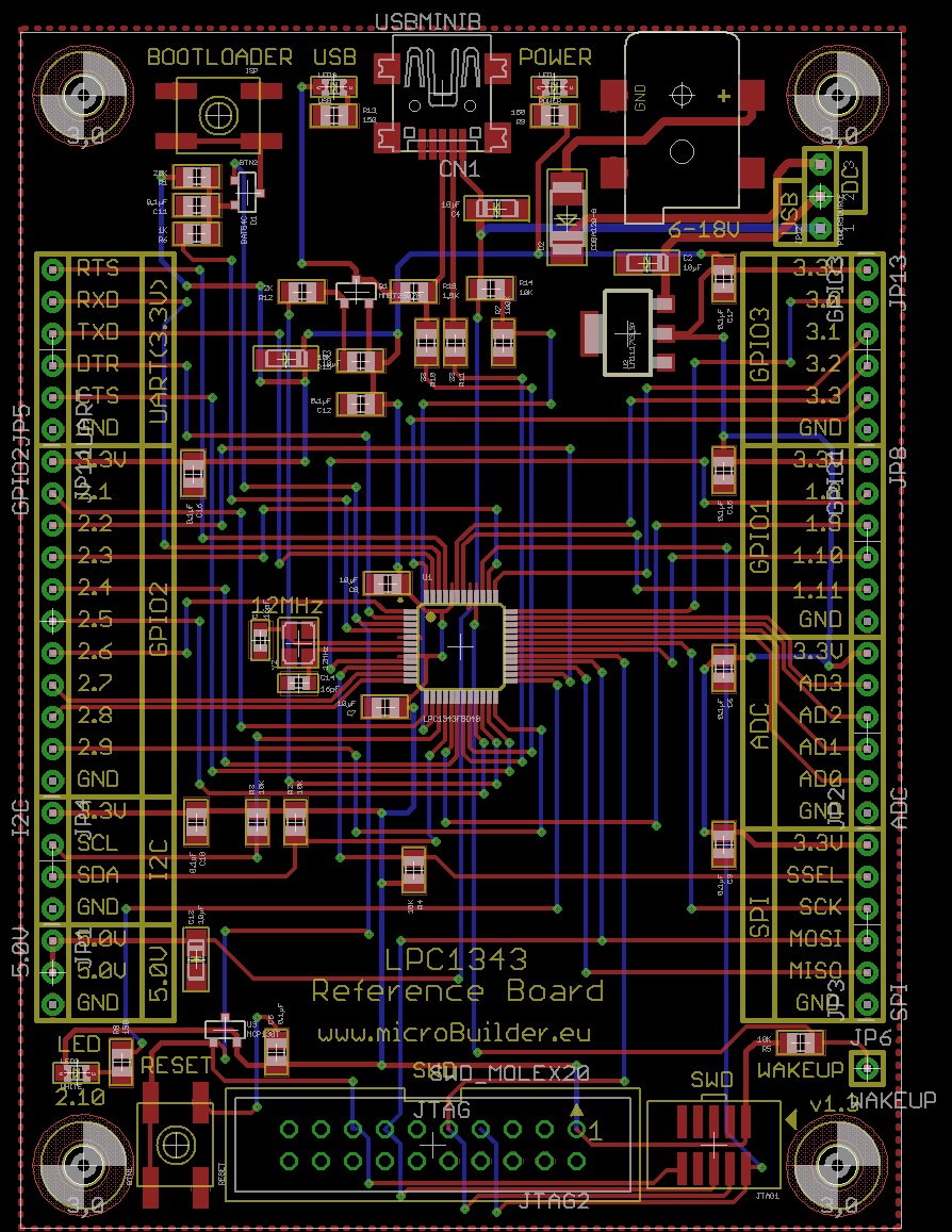
PCB هدر برد در نرم افزار قدرتمند طراحی برد مدارچاپی EAGLE طراحی شده است. شما می توانید آن را به فایل آلتیوم دیزاینر تبدیل و حتی آنرا ویرایش کنید . کتابخانه استفاده شده در سایت طراحش موجود می باشد و می توانید آن را دانلود کنید . در ادامه لینک سازنده طراح برد برای رعایت زحمت های کشیده شده و همچنین دانلود فایل های تکمیلی آورده شده است .
فایل های آموزشی هدربرد Cortex-M3 LPC1343
- Debugging the CodeBase in LPCXpresso
- GCC Development Environment for ARM
- Using CodeLite with the LPC134 Part 1
- Using CodeLite with the LPC1343 Part 2
- Using PWM on the LPC1343
- Freaklabs RF Antennas with the LPC1343
- Using Chibi 802.15.4 Wireless Stack
- Benchmarking in code using DWT
نمونه کد های هدربرد و مستندات هدربرد Cortex-M3 LPC1343 :
- LPC1343 Code Base Active Development
- LPC1343 Code Base Major releases
- LPC1343 Code Base Documentation
- TFT Graphics Sub-System Documentation
- TFT LCD CLI Commands
آموزش ها:
آموزش کار با نرم افزار STM32CubeMX
راه اندازی پروتکل سریال میکروکنترلرهای STM32
سایت منبع و رفع مسئولیت : microbuilder.eu
اگر این نوشته برایتان مفید بود لطفا کامنت بنویسید.