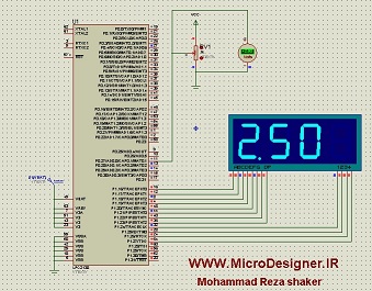
راه اندازی قسمت ADC میکروکنترلر LPC2138
همانطور که می دونید فقط تعدادی از میکروکنترلرهای ARM توی پرتیوس هستن و در اکثر دانشگاه ها برای راحتی کار از این سری از میکروکنترلر ها برای تدریس استفاده می شود .
مثالی از راه اندازی قسمت ADC میکروکنترلر LPC2138 را که کدش در کامپایلر کیل نوشته شده و در پروتیوس شبیه سازی شده
پیش نیاز های پروژه :

نرم افزار پروتیوس برای شبیه سازی
کامپایلر کیل برای کامپایل کد های C
قطعات استفاده شده :
سون سگمنت که بصورت مالتی پلکس بسته شده
پتانسیومتر برای ایجاد ولتاژ دلخواه
میکروکنترلر lpc2138
دانلود مثال راه اندازی قسمت ADC میکروکنترلر LPC2138
منبع و نویسنده برنامه : محمد رضا شاکر
مطالب مرتبط :
آموزش کار با نرم افزار STM32CubeMX
راه اندازی پروتکل سریال میکروکنترلرهای STM32
اگر این نوشته برایتان مفید بود لطفا کامنت بنویسید و همچنین میتوانید اپلیکیشن اندرویدی آموزش الکترونیک را هم نصب کنید.

سلام.
چطور میتونم یک ولتاژ سه فاز به ARM متصل لنم ات داخل میکرو از اندازه و فاز شان تو محاسبات استفاده کنم؟؟/
با تشکر
سلام . دوتا لینک زیر را ببینید :
https://www.rroij.com/open-access/design-and-development-of-pic-microcontrollerbased-3-phase-energy-meter.pdf
و لینک زیر :
https://melec.ir/industrial-automation-board-3input-3output-rs232/
اگربخوایم ولتاژ روی ال سی دی نمایش بدیم باید چه کدی استفاده کنیم؟
لینک زیر را ببینید :
https://melec.ir/%D9%87%D8%AF%D8%B1%D9%81%D8%A7%DB%8C%D9%84-%D8%B1%D8%A7%D9%87-%D8%A7%D9%86%D8%AF%D8%A7%D8%B2%DB%8C-lcd-%DA%A9%D8%A7%D8%B1%D8%A7%DA%A9%D8%AA%D8%B1%DB%8C-%D8%A8%D8%B1%D8%A7%DB%8C-lpc2368-%D9%88lpc2132/
سلام من میخوام با استفاده از سنسور و pwm فن یا هیتر رو راه اندازی کنم این کد و پروتِسم هست ولی نمیدونم کجاش گیر داره که از pwm خروجی نمیگیرم
FOSC = 12MHz
CCLK = 60MHz
PCLK = 15MHz
*/
#include
#include
#include “config.h”
#include “pwm.h”
/****************LCD DIRECTIVES***************/
#define LCD_CLEAR 0x01
#define CURSOR_OFF 0x0C
#define FIRST_ROW 0x80
#define SECOND_ROW 0xC0
#define Enable_Pulse() IOSET0|=1<<EN;Delay_ms(1);IOCLR0=1<<EN;Delay_ms(1);
/*Pin Configuration for LCD*/
#define RS 2
#define RW 3
#define EN 4
/*********************************************/
char avrage_temp=0 ;
char sensor_temp=0 ;
char keypad_temp=0 ;
char fan_pwm=0 ;
char heater_pwm=0 ;
char key ;
unsigned char i;
/*********************************************/
unsigned char msg[] = "EMBEDDED LAB";
unsigned char LM35_Temperature[] = "TEMP. MONITOR";
unsigned char data_received[] = "TEMP VALUE:";
unsigned char ones,tens,hundreds,thousands;
unsigned long temp;
/**************Function Prototypes************/
void UART0_Init(void);
void UART0_Write(unsigned char value);
void UART0_Write_Text(unsigned char msg[]);
unsigned char UART0_Read(void);
void Lcd_Init(void);
void Lcd_Cmd(unsigned char value);
void Lcd_Write(unsigned char value);
void Lcd_Write_Text(unsigned char msg[]);
void Lcd_Data_Shift(unsigned char value);
void ADC0_Init(void);
unsigned int ADC0_Read(void);
//////////////////////////TABE DELAY////////////////////////
void Delay_ms(unsigned long times);
void msDelay(int d) {
int i,j;
long c =0;
d=d*2 ;
for(i=0;i<d;i++){
for(j=0;j<1000;j++){
c++;
}
}
}
/////////////////////////////////////////ATBE ADC//////////////////////
/*********************************************/
unsigned long adc_data;
int main()
{
Lcd_Init();
UART0_Init();
Delay_ms(10);
UART0_Write_Text(msg);
UART0_Write(10);
UART0_Write(13);
Lcd_Write_Text(msg);
Lcd_Cmd(SECOND_ROW);
Lcd_Write_Text(LM35_Temperature);
UART0_Write_Text(LM35_Temperature);
UART0_Write(10);
UART0_Write(13);
Delay_ms(500);
Lcd_Cmd(LCD_CLEAR);
Lcd_Write_Text(data_received);
Lcd_Cmd(SECOND_ROW);
pwm4_init();
pwm4_out(127);
pwm6_init();
pwm6_out(120);
ADC0_Init();
while(1)
{
adc_data = ADC0_Read();
adc_data = adc_data*3300;
adc_data = adc_data/1023; //Value of Voltage in Milli Volts
/*Display Text on LCD*/
temp = adc_data;
ones = temp % 10;
temp = temp / 10;
tens = temp % 10;
temp = temp / 10;
hundreds = temp % 10;
temp = temp / 10;
thousands = temp % 10;
////////////////////////////////////////////////////
///////////////////////////////////////////////
ones |= 0x30;
tens |= 0x30;
hundreds |= 0x30;
thousands |= 0x30;
Lcd_Cmd(SECOND_ROW);
Lcd_Write(thousands);
Lcd_Write(hundreds);
Lcd_Write(tens);
Lcd_Write('.');
Lcd_Write(ones);
Lcd_Write(' ');
Lcd_Write('C');
Delay_ms(10);
pwm4_out(i);
Delay_ms(150);
i=i+5;
} ;
}
/****************Function Definition**********/
/****************Delay Function***************/
void Delay_ms(unsigned long times)
{
unsigned long i,j;
for(j=0;j<times;j++)
for(i=0;i<7500;i++);
}
/*********************************************/
/*****************LCD Functions***************/
void Lcd_Init(void)
{
PINSEL0 = 0x00;
IODIR0 |= (1<<RS); //RS Pin as Output Pin
IODIR0 |= (1<<RW); //RW Pin as Output Pin
IODIR0 |= (1<<EN); //EN Pin as Output Pin
IODIR0 |= 0x00ffff00; //P0.10 to P0.17 as Data Line of LCD
Lcd_Cmd(0x38); //Send 8-bit initialization command to lcd
Delay_ms(10);
Lcd_Cmd(CURSOR_OFF); //Cursor OFF
Delay_ms(10);
Lcd_Cmd(LCD_CLEAR);
Delay_ms(1);
Lcd_Cmd(FIRST_ROW);
}
void Lcd_Data_Shift(unsigned char value)
{
/*
This Function will shift the eight bit data stored in variable value,
to the Port Pin P0.8 to P0.15 Successfully.
*/
unsigned char i;
for(i=0;i<10;i++)
{
if(value & 0x01)
{
IOSET0 |= (1<<(i+10));
}
else
{
IOCLR0 |= (1<> 1;
}
}
void Lcd_Cmd(unsigned char value)
{
/*Configure LCD for receiving Command Data*/
IOCLR0 |= (1<<RS);
IOCLR0 |= (1<<RW);
IOSET0 |= (1<<EN);
Lcd_Data_Shift(value);
Enable_Pulse();
}
void Lcd_Write(unsigned char value)
{
/*Configure LCD for receiving Display Data*/
IOSET0 |= (1<<RS);
IOCLR0 |= (1<<RW);
IOSET0 |= (1<<EN);
Lcd_Data_Shift(value);
Enable_Pulse();
}
void Lcd_Write_Text(unsigned char msg[])
{
while(*msg)
{
Lcd_Write(*msg);
msg++;
}
}
/*********************************************/
/***************UART-0 Functions**************/
void UART0_Init(void)
{
PINSEL0 = 0x00000005; //P0.0 as TX0 and P0.1 as RX0
U0LCR = 0x83; //Enable access to Divisor Latches
//and Set 8 bit Character Length with 1 Stop bit and Parity Disabled
//Access to Divisor Latches is Enabled, in order to write Baud Rate Generator Registers
//Values to be written in Baud Rate Registers U0DLM and U0LL
/*
Formula is
Baud_Rate = PCLK*MulVal / [(16*(256*U0DLM+U0DLL)*(MulVal + DivAddVal))]
Example:-
MulVal = 1;
DivAddVal = 0;
Baud_Rate = 9600;
PCLK = 15MHz
U0DLM = 0;
Hence,
U0DLL = 15000000/(9600*16) = 97.65625 = 98
U0DLL = 98 = 0x62
*/
U0DLM = 0x00;
U0DLL = 0x62; //Baud Rate of 9600
U0LCR = 0x03; //Disable Access to Divisor Latches
}
void UART0_Write(unsigned char value)
{
/*
THRE bit can be extracted by this U0LSR & 0x20
THRE = 0 means data is present.
THRE = 1 means register is empty.
In order to transmit data, we have to wait will the THRE = 1,
then only we can transmit data.
*/
while(!(U0LSR&0x20)); //THRE = 0 stay here
U0THR = value;
}
void UART0_Write_Text(unsigned char msg[])
{
while(*msg)
{
UART0_Write(*msg);
msg++;
}
}
unsigned char UART0_Read(void)
{
/*
Receiver Data Ready = U0LSR.0 bit
RDR bit can be extracted by this U0LSR & 0x01
RDR = 0 means no Data is Received in U0RBR
RDR = 1 means that Data is present in U0RBR
*/
while(!(U0LSR & 0x01)); //RDR = 0 stay here
return (U0RBR);
}
/*********************************************/
/*****************ADC Functions***************/
void ADC0_Init(void)
{
/*************Initialize ADC AD0.0*************/
AD0CR = 1<<21; //A/D is Operational
AD0CR = 0<<21; //A/D is in Power Down Mode
PCONP = (PCONP &0x001817BE) | (1UL<<12);
PINSEL0 = 0x00;
PINSEL1 = 0x00400000; //P0.27 is Configured as Analog to Digital Converter Pin AD0.0
AD0CR = 0x00200401; //CLKDIV=4,Channel-0.0 Selected,A/D is Operational
/*
A/D Clock = PCLK /(CLKDIV+1);
*/
/**********************************************/
}
unsigned int ADC0_Read(void)
{
unsigned long adc_data;
AD0CR |= 1UL<> 6;
adc_data = adc_data & 0x3FF; //Clearing all other Bits
return (adc_data);
}
void pwm (void)
{
pwm4_init();
pwm4_out(127);
pwm6_init();
pwm6_out(230);
while(1)
{
}
}
/*********************************************/